The preferred growth orientation of Ti thin film on MgO(100) substrate
 Jun Yang1,2,3
  Yong Fang
 Pak Yan Moh
- 1Faculty of Science and Natural Resources, Universiti Malaysia Sabah, Kota Kinabalu, Sabah, Malaysia
- 2School of Materials Science and Engineering, Sichuan University of Science and Engineering, Zigong, China
- 3Material Corrosion and Protection Key Laboratory of Sichuan Province, Sichuan University of Science and Engineering, Zigong, China
- 4Zigong Huidong Experimental School, Zigong, China
- 5State Key Laboratory for Mechanical Behavior of Materials, Xi’an Jiaotong University, Xi’an, China
Understanding the preferred growth orientation of metal films is of great significance for optimizing film properties and preparing films with special structures. However, early works mainly focused on the preferred growth orientations of FCC and BCC metal films, the preferred growth orientation of HCP metal films and its formation mechanism are unclear. In this work, Ti film was deposited on MgO(100) substrate by magnetron sputtering at 523 K. The preferred growth orientation of Ti film and its formation mechanism were studied by experiment and first-principles calculation. XRD results found the preferred growth orientations of Ti film on MgO(100) substrate were Ti(001), Ti(100), and Ti(101), with Ti(001) being the most favored. First-principles calculation results showed the preferred growth orientation of the Ti film on the MgO(100) substrate was determined by a combination of interface separation work and lattice strain.
1 Introduction
Composite materials consisting of metal thin films and ceramic substrates (metal/ceramic) are widely used in various fields such as coating, sensors, solar cell, and microelectronic device manufacturing (Chen et al., 2021; Yuan et al., 2021; Ibrahim et al., 2022; Qin, 2022; Wu et al., 2022), because metal thin films can be precisely engineered to exhibit specific structures and properties, while ceramic substrates provide stability and insulation, allowing for customized functionalities. Taking Nb/MgO (100) as an example, it has been found that the growth direction of niobium thin films can be controlled by controlling deposition conditions, and niobium thin films with different orientations exhibited different superconducting behaviors (Beringer et al., 2013). Typically, when metal film is deposited on ceramic substrate, the film tends to exhibit one or more preferred growth directions (Lei, Yan, and Xiao Nan, 2018; Gao et al., 2019). By studying these preferred growth directions, the crystal structure of the metal film can be determined. This knowledge helps us to understand the arrangement of atoms during film deposition, thereby facilitating the formation of specific crystal planes.
In the studies of preferred growth orientations, MgO (magnesium oxide) is often used as a substrate material because of its simple sodium chloride structure and the ease of obtaining pristine surfaces. When Cu (Zhang et al., 2015), Ag (You, Liang, and Wei, 2018), Al (Yang et al., 2015) and Ni (Lukaszew et al., 2003) thin films are deposited on MgO substrates, these films tend to grow in alignment with the substrate’s orientation. This is known as the cubic-on-cubic orientation relationship between FCC metals and MgO substrates (Ernst, 1995). In the case of BCC metals [e.g., Nb (Fu et al., 2014), V (Du et al., 2017), Cr (Wang et al., 2011), and Fe (Serizawa et al., 2019)], the most preferred growth directions on MgO(100), MgO(110), and MgO(111) substrates are commonly [100], [112], and [110], respectively. Overall, the most preferred growth orientations of FCC and BCC metals on MgO substrates are widely recognized. However, in contrast to the extensive studies of BCC and FCC metal films, limited research has been dedicated to exploring the preferred growth orientation of HCP metal films (Vipin et al., 2008; Yongzhong et al., 2008; Moskovkin et al., 2021). The preferred growth orientations and formation mechanism of HCP structured metal films on MgO substrates are currently unclear.
One reason is that the preferred growth orientation of HCP structured metal films is significantly influenced by deposition conditions. Taking titanium, for example, titanium has a HCP structure at room temperature and normal pressure, and titanium thin films possess excellent corrosion resistance and friction resistance, which are related to the crystal orientation of the films (Song et al., 2012). Kado utilized electron beam evaporation at 273 K to deposit Ti thin films on MgO(100) substrate (Kado, 2000). It was observed that films with a thickness below 4 nm possess an FCC structure. Conversely, films with a thickness exceeding 6 nm exhibit an HCP structure, with the orientation of Ti(001)//MgO(100). However, Harada et al. reported the preferred orientation is Ti(101)//MgO(100) when the sample is prepared at room temperature and subjected to heat treatment at 1173 K for 30 min (Harada and Ohkoshi, 1997). Vipin et al. (2008) investigated the growth orientation of titanium films on Si(100) substrates in the temperature range of 373–873 K. They found that the preferred growth orientations for the titanium films were (100), (110), and (101). Moreover, they observed that the optimal growth direction varied with different substrate temperatures. Thus, there is still controversy regarding the most stable growth orientation of Ti film on MgO(100) substrate. Another significant reason is the complexity of the atomic arrangement in HCP structured metals. For instance, the atomic arrangement on the (001) and (100) crystal planes of HCP structured metals differs, and the [101] crystal direction in the HCP structure is not perpendicular to the (101) crystal plane. As a result, the intricate crystal structure, combined with an uncertain stable interface structure, presents challenges in modeling the interface between HCP structured metals and MgO substrates. During the initial stages of computer simulation research on metal/MgO interfaces, the focus was primarily on FCC and BCC metals (Benedek et al., 2000; Du et al., 2016; Fang, Zhang, and Zhang, 2016; Yang et al., 2023). To our best knowledge, there is currently no computer simulation study on the interface structure between Ti film and MgO substrate.
Understanding the preferred growth directions of metal thin films involves various factors such as crystal structure, lattice matching, surface energy, and substrate orientation. One perspective suggests that the preferred growth orientation is primarily attributed to a system’s effort to decrease the nucleation barrier through the formation of a low-energy interface (Herr, 2000). Thus, calculating the interface energies of different interface models allows us to predict the preferred growth orientation. Based on this viewpoint, Fu et al. conducted experimental and first-principles calculations to examine the interface structures of Nb/MgO(100) (Fu et al., 2014), Fe/MgO(100), and V/MgO(100) (Du et al., 2017). They discovered that the stable interface observed in the experiment exhibited the largest interface separation work for all three systems. They suggested the interface separation work played a crucial role in determining the preferred growth orientation. However, Fu’s research solely focused on the most preferred growth orientation between BCC metals and MgO(100) substrate. It remains uncertain whether calculating the interface separation work can determine the preferred growth orientation of HCP structured metal films.
In order to clarify the preferred growth orientation of Ti film on MgO(100) substrate and explore its formation mechanism, in this study, we will begin by applying the magnetron sputtering technique to coat a titanium film onto an MgO(100) substrate. Subsequently, XRD and SEM analysis will be employed to determine the preferred growth orientation and the cross-section morphology of the film. Additionally, First-principles calculation method will be used to investigate the underlying formation mechanism of the preferred growth orientation. The findings indicate that the (001) orientation is the most favored growth orientation for the Ti thin film on the MgO(100) substrate. The preferred growth orientation is determined by the combination of interface separation work and lattice strain, which is different from the situations in BCC metal films on MgO(100) substrates.
2 Material and methods
Ti thin film was deposited on single crystal MgO(100) substrate by means of direct current magnetron sputtering with ultra-high vacuum multifunctional magnetron sputtering equipment (SD-550). The purity of the sputtering target (5 cm diameter and 0.5 cm thick) was 99.99%, and the single crystal MgO(100) substrate (10 mm × 10 mm × 0.5 mm) was polished with a surface roughness less than 3 nm. Both the target and polished substrate were provided by Hefei Microcrystalline Technology Co., Ltd in China. Prior to the deposition, the vacuum chamber was evacuated till the pressure is better than 2.6 × 10⁻⁴ Pa. After that, the sputtering was carried out in an Argon atmosphere with the gas pressure of 0.66 Pa. The distance between target and substrate, deposition temperature, deposition power and deposition time were set to 5 cm, 523 K (250°C), 100 W, and 60 min, respectively. After the sample is prepared, the preferred growth orientation of Ti film was characterized by X-ray diffraction (XRD, Bruker, D2 PHYSER), and the cross-section view of the sample was investigated by scanning electron microscopy (SEM, TESCAN, VEGA3).
Figure 1A displays the primitive unit cell of titanium (Ti) with HCP structure. The optimized lattice constants of this model are a = b = 3.019 Å, and c = 4.779 Å. The computed lattice constant is slightly larger than the experimental value due to the utilization of GGA (Perdew and Zunger, 1981) as the exchange correlation function during structure optimization. Ti(001) plane is the terminal plan (x-o-y plane) in this model. Similarly, Figures 1B, C depict the smallest unit cells featuring the terminal planes of Ti(100) and Ti(101) respectively. Table 1 provides the structural information of Ti three unit cells. Figure 1D showcases the unit cell of magnesium oxide (MgO) with the optimized lattice constant of 4.299 Å.
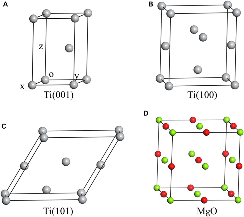
FIGURE 1. The crystal structures of three Ti unit cells and MgO unit cell, including Ti(001) (A), Ti(100) (B), Ti(101) (C) and MgO (D).
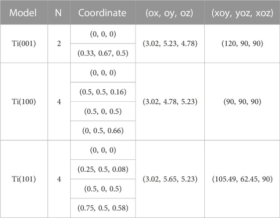
TABLE 1. Structure information of three Ti unit cells, including number of atoms (N), atomic fractional coordinates, lattice constants [(ox, oy, oz), unit in Å], and angles between lattice vectors [(xoy, yoz, xoz), unit in °].
Using the “interface builder” toolbox in Atomistk ToolKit (ATK) software (Smidstrup et al., 2020), we construct possible coherent interface structures made up of two surfaces. The schematic diagram is depicted in Figure 2. Initially, we identify the potential unit cells within a super-cell for both surfaces, as illustrated in Figures 2A, B [denoted as (Ai, Ai+1, Ai+2, … ) and (Bi, Bi+1, Bi+2, … )]. The lattice vectors of any two-dimensional unit cells on the two surfaces can be represented as [(a1x, 0), (b1x, b1y)] and [(a2x, 0), (b2x, b2y)]. Subsequently, we match the unit cells one by one to create coherent interfaces, as shown in Figure 2C. The coherent interface is formed by applying two positive strains (ε11, ε22) and one shear strain (ε12) on a single unit cell, with the transformation expressed as
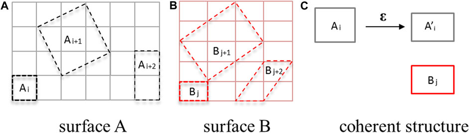
FIGURE 2. Schematic picture of establishing coherent interface model, including surface A (A), surface B (B) and coherent interface building (C).
Interface separation work (Wsep) is commonly used to quantify the strength of interface bonding. It is defined as the energy required to separate an interface into two surfaces (Finnis, 1996). The formula for Wsep is as Wsep = (ETi + EMgO–ETi/MgO)/S, where S represents the interface area, and ETi and EMgO are the total energies of the separated Ti and MgO slabs, respectively. ETi/MgO represents the total energy of the entire interface system with the optimized interface distance. The optimized interface distance can be determined by calculating the total energy of the system as a function of the interface distance. Additionally, the transfer of charges along the interface will be analyzed by calculating electron density difference and atomic Mulliken charge population (Fu et al., 2014). The density functional theory calculation module in ATK software (Smidstrup et al., 2020) is chosen to do all calculations. Single Zeta plus Polarization basis set (SZP) is used to describe the electron wave function. Polarized Perdew-Burke-Emzerh of generalized-gradient approximation (GGA-PBE) is selected as the exchange and correlation function (Perdew and Zunger, 1981). Grid mesh cut-off energy is set to 80 Hartree. K-point mesh of 13 × 13×1 is chosen for total energy calculation for all calculation models. The rest calculation parameters are defaulted by the software.
3 Results and discussion
3.1 The preferred growth orientations of Ti film on MgO(100) substrate in experiment
Figure 3 shows XRD patterns of Ti film on MgO(100) substrate by magnetron sputtering at 523 K. The substrate exhibits extremely high peaks (135 kilo-counts) because of its single crystal structure. For Ti film, Ti(002) shows the strongest reflection (3.4 kilo-counts), indicating that the film is strongly textured with the Ti(002) plane. At the same time, Ti(100), Ti(101) and Ti(004) show small diffraction peaks with several hundred counts. Thus, titanium film exhibits three preferred growth orientations, namely, Ti(001), Ti(100) and Ti(101), with Ti(001) being the most preferred direction of growth. The thickness of the Ti film was measured by taking cross-sectional view of the sample by SEM (Figure 4). In the picture, the film is deposited along z direction. The interface between Ti and MgO substrate is clear and flat. The titanium film exhibits a smooth surface. The overall thickness of the titanium film is around 17.5 μm, including a transition region of 1.5 μm and a clear textured region of 16 μm.
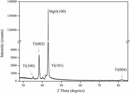
FIGURE 3. XRD patterns of Ti film deposited on MgO(100) substrate by magnetron sputtering at 523 K.
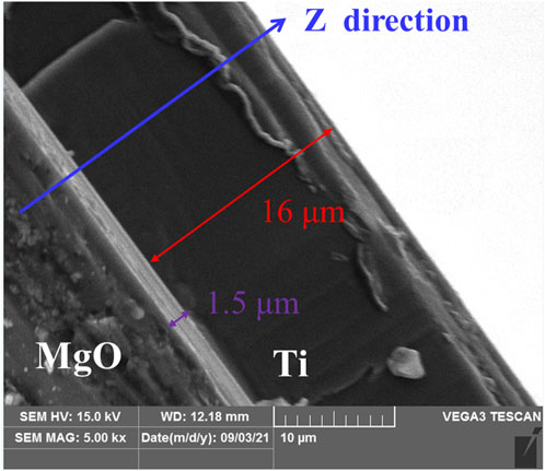
FIGURE 4. Cross-sectional view of Ti film on MgO(100) substrate deposited by SEM.
3.2 Understanding the preferred growth orientations of Ti film on MgO(100) substrate by simulation
Nine coherent interface models of Ti/MgO(100) are constructed using the “interface builder” toolbox. To determine the optimal interface distance, the total energy of each model is calculated. Figure 5 illustrates one calculation result of a Ti(001)//MgO(100) interface model with an average strain ε of 4.50%. The system exhibits the lowest energy when the interface distance is 3.0 Å. This indicates that the optimized interface distance of the model is 3 Å. When the interface distance is greater or less than 3 Å, the system will be in a non-equilibrium state, corresponding to higher system energy. By calculating the individual energies of Ti and MgO slabs, the interfacial separation energy of the model can be obtained (0.048 eV/Å2).
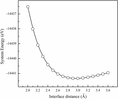
FIGURE 5. Calculation result of system energy as a function of interface distance for one Ti(001)//MgO(100) coherent interface model (ε = 4.50%).
Using the same computational procedure as illustrated in Figure 5, the “system energy-interface distance” calculations were performed for the remaining eight computational models. The results indicated a similar trend for the “energy-interface distance” of each model, whereby the system energy reaches its minimum value at a specific interface distance. Based on the optimized interface distance, we can calculate the energies of Ti and MgO slabs, and get the lattice strains and interface separation works for the nine Ti/MgO(100) models, are presented in Figure 6. Firstly, one model belonging to Ti(101)//MgO(100) (labeled as “1”) exhibits the highest interface separation work (0.131 eV/Å2). The maximum interface separation work indicates the strongest interfacial chemical bonding. However, our XRD results show that Ti(001) is the preferred growth orientation on MgO (100) substrate, rather than Ti(101). Therefore, it is not feasible to solely determine the most preferred orientation of the Ti film on the MgO(100) substrate by calculating the interface energy. At the same time, the model with the maximum interfacial separation work (ε = 8.98%) does not have the minimum lattice strain, indicating there is no direct relationship between lattice strain and interfacial separation work.
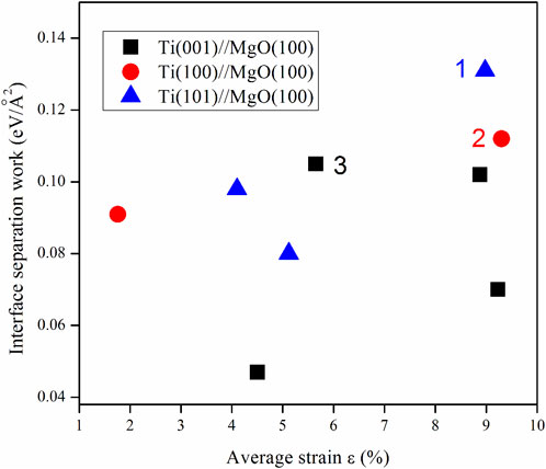
FIGURE 6. Calculation results of interface separation works for the nine Ti/MgO(100) coherent interface models.
Secondly, There are two models labeled as “2” and “3”, which respectively belong to Ti(100)//MgO(100) and Ti(001)//MgO(100). They possess similar interface separation works (0.112 and 0.105 eV/Å2), with their values only being smaller than model 1. The growth orientation of Ti film in model 3 is consistent with the experimental result, indicating a (001) orientation. Additionally, model 3 exhibits the smallest lattice strain (ε = 5.65%) among the three models. On one hand, previous investigations on several metal/MgO systems [Nb/MgO(100) (Fu et al., 2014), Nb/MgO(110) (Fang, Zhang, and Zhang, 2016), Nb/MgO(111) (Fu et al., 2014), Fe/MgO(100), V/MgO(100) (Du et al., 2017)] have demonstrated that the preferred orientation of BCC metal films can be determined by calculating the interfacial separation works. The interface separation work (Wsep) is a crucial factor for assessing metal film growth. In addition, lattice strain is an important factor to determine the orientation of Ti crystal on the MgO substrate and makes the between two misfit crystal planes compatible. However, the nine coherent interfaces do not account for the influence of dislocations on interface separation work. Considering the XRD experimental findings, the interface separation work and lattice strain of the three models (model 1, model 2 and model 3), we propose that the most preferred growth of titanium thin films on MgO (100) substrates is determined by the combination of interface separation work and lattice strain, and model 3 [Ti(001)//MgO(100)] gives the most preferred growth orientation of Ti film on MgO(100) substrate.
Currently, there is no relevant simulation study on simultaneously considering the influence of interface energy and lattice strain energy on the growth of preferred interfaces. In present work, we just built coherent models to study the interface structure of Ti/MgO(100), and did not consider the energy caused by lattice strain. For real metal/oxide interfaces, the interface type is typically semi-coherent. To clarify the role of interface energy and lattice strain energy in the formation of preferred interfaces, a possible research direction is to construct semi-coherent interface models, and quantitatively analyze the roles of interface energy and lattice strain energy in the formation of preferred interfaces. It should be noted that in this study, a static approach was adopted to predict the preferred orientation of Ti crystal structures on MgO(100) substrate. This is based on the assumption that the experimentally obtained preferred interface structure is in equilibrium. However, the deposition of metal films is a dynamic process, and the interface structure between the metal and oxide is influenced by various factors. If the substrate is rough or if the metal film undergoes structural phase transitions during the deposition process, this method cannot be used to predict the preferred interface structure. In addition, in the XRD diffraction peaks, apart from Ti(001), there are also Ti(101) and Ti(100). We speculate that model 1 and model 2 correspond to the diffraction peaks of Ti(101) and Ti(100) in XRD. The two structures (model 1 and model 2) are also preferred growth orientations of Ti film on MgO(100) substrate.
3.3 The preferred interface structures between Ti film and MgO(100) substrate
Titanium film exhibits three preferred growth orientations on MgO(100) substrate, namely, Ti(001), Ti(100) and Ti(101), with Ti(001) being the most favored direction of growth. Figure 7 presents the crystal structures of the three interface models (model 1, model 2, and model 3), and Table 2 provides the detailed structural information. Previous studies have indicated that the bonding strength at the interface primarily depends on the arrangement of atoms near the interface. In Figure 7, all three models share the same substrate structure but differ in the arrangement of titanium atoms in the film. In Model 1 [Ti(101)//MgO(100)], as indicated by the dashed lines, the first-layer titanium atom is positioned directly above the oxygen atom on the MgO(100) substrate. The second-layer titanium atom, which is in close proximity to the first layer, is almost situated at the top of the oxygen atom. The O-atop position is known to be the most stable adsorption site for a single metal atom on the MgO(100) surface (Du et al., 2017). As a result, the two titanium atoms in Model 1 are located at the most stable adsorption sites, resulting in the highest interfacial binding strength. Conversely, the second titanium atom in Model 2 and Model 3 is not positioned at the top of the oxygen atom, leading to a smaller value for interfacial separation work.
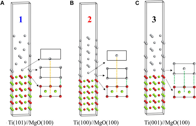
FIGURE 7. Crystal structures of three Ti/MgO(100) coherent interface models with the interface separation works of 0.131 (A), 0.112 (B) and 0.105 eV/Å2 (C). The atomic matching at the interface is indicated by dashed lines, where the matching between the first layer of titanium and the substrate atoms is represented by green dashed lines, and the matching between the second layer of titanium atoms and the substrate atoms is represented by yellow dashed lines.
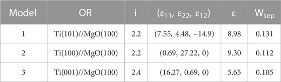
TABLE 2. Structure information of three Ti/MgO(100) coherent interface models, including orientation along the interface (OR), interface distance (i, unit in Å), lattice strain [(ε11, ε22, ε12), unit in %], average strain (ε, unit in %), and interface separation work (Wsep, unit in eV/Å2).
In addition, we also calculated the interface electronic structures of the three models. The results of electron density difference (△ρ = ρA/B-ρA-ρB) and Mulliken charge difference (△M = MA/B-MA-MB) for model 1, 2, and 3 are shown in Figure 8. In the electron density difference maps, the blue isosurface represents electron loss, while the light red isosurface represents electron aggregation. In all three models, titanium atoms lose electrons, while the magnesium oxide substrate gains electrons. These electron gains and losses occur at the atoms near the interface, indicating that the arrangement of atoms on both sides of the interface determines the strength of chemical bonds at the interface. Regarding the Mulliken charge difference results, the atoms in model 1 [Ti(101)//MgO(100)] on both sides of the interface experience the strongest electron gain and loss, resulting in the strongest chemical bonding. However, for model 2 and model 3, the Mulliken values suggest that the interface bonding is relatively weak, corresponding to a smaller interface separation work.
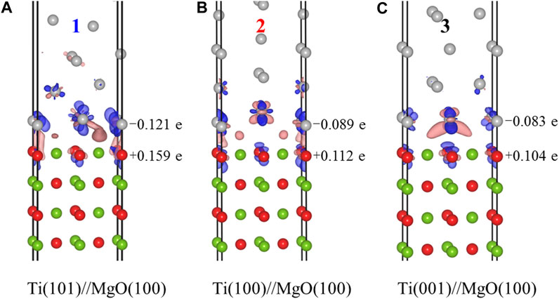
FIGURE 8. Calculation results of electron density difference and Mulliken charge difference for the three Ti/MgO(100) interface models, including Ti(101)//MgO(100) (A), Ti(100)//MgO(100) (B), and Ti(001)//MgO(100) (C).
4 Conclusion
To summarize, we utilized magnetron sputtering to deposit a Ti film onto an MgO(100) substrate. The analysis of XRD and first-principles calculations allowed us to examine the preferred growth orientations of the film and understand its formation mechanism. Our findings revealed three preferred growth orientations: Ti(001), Ti(100), and Ti(101), with Ti(001) being the most favored. Furthermore, the calculation results demonstrated that the preferred growth orientation of the Ti film on the MgO(100) substrate was determined by a combination of interface separation work and lattice strain.
Data availability statement
The datasets presented in this article are not readily available because no comment. Requests to access the datasets should be directed to fangyongxinxi@163.com.
Author contributions
JY: Investigation, Methodology, Writing–original draft. PM: Data curation, Writing–review and editing. SB: Visualization, Writing–original draft. YJ: Writing–review and editing, Project administration, Investigation. YF: Writing–review and editing, Resources. YS: Investigation, Writing–review and editing.
Funding
The author(s) declare financial support was received for the research, authorship, and/or publication of this article. This work was supported by the Malaysian Ministry of Higher Education under the Fundamental Research Grant Scheme (FRGS/1/2019/STG01/UMS/02/2), the Opening Project of State Key Laboratory for Mechanical Behavior of Materials (No. 20212304), the Opening Project of Material Corrosion and Protection Key Laboratory of Sichuan province (No. 2020CL15), the talent introduction project of Sichuan University of Science and Engineering (No. 2017RCL34).
Acknowledgments
The authors express their gratitude to Xiangdong Ding at Xi’an Jiaotong University for providing valuable insights and assistance with calculations.
Conflict of interest
The authors declare that the research was conducted in the absence of any commercial or financial relationships that could be construed as a potential conflict of interest.
Publisher’s note
All claims expressed in this article are solely those of the authors and do not necessarily represent those of their affiliated organizations, or those of the publisher, the editors and the reviewers. Any product that may be evaluated in this article, or claim that may be made by its manufacturer, is not guaranteed or endorsed by the publisher.
References
Benedek, R., Alavi, A., Seidman, D. N., Yang, L. H., Muller, D. A., and Woodward, C. (2000). First principles simulation of a ceramic/metal interface with misfit. Phys. Rev. Lett. 84 (15), 3362–3365. doi:10.1103/PhysRevLett.84.3362
Beringer, D. B., Roach, W. M., Clavero, C., Reece, C. E., and Lukaszew, R. A. (2013). Characterization of two different orientations of epitaxial niobium thin films grown on MgO(001) surfaces. J. Appl. Phys. 114 (22). doi:10.1063/1.4837595
Chen, L., Li, Y. F., Xiao, B., Gao, Y. M., Wang, J., Yi, D. W., et al. (2021). Chemical bonding, thermodynamic stability and mechanical strength of Ni3Ti/α-Al2O3 interfaces by first-principles study. Scr. Mater. 190, 57–62. doi:10.1016/j.scriptamat.2020.08.021
Du, J. L., Fang, Y., Fu, E. G., Ding, X., Yu, K. Y., Wang, Y. G., et al. (2016). What determines the interfacial configuration of Nb/Al2O3 and Nb/MgO interface. Sci. Rep. 6, 33931. doi:10.1038/srep33931
Du, J. L., Zhang, L. Y., Fu, E. G., Ding, X., Yu, K. Y., Wang, Y. G., et al. (2017). Comparison of interface structure of BCC metallic (Fe, V and Nb) films on MgO (100) substrate. Appl. Surf. Sci. 410, 585–592. doi:10.1016/j.apsusc.2016.10.117
Ernst, F. (1995). Metal-oxide interfaces. Mater. Sci. Eng. Rep. 14 (3), 97–156. doi:10.1016/0927-796x(95)80001-8
Fang, Y., Zhang, L. Y., and Zhang, H. L. (2016). Predicting the interface structure of Nb thin film grown on MgO(110) substrate. Mater. Lett. 183, 338–340. doi:10.1016/j.matlet.2016.07.101
Finnis, M. W. (1996). The theory of metal-ceramic interfaces. J. Phys. Condens. Matter 8 (32), 5811–5836. doi:10.1088/0953-8984/8/32/003
Fu, E. G., Fang, Y., Zhuo, M. J., Zheng, S. J., Bi, Z. X., Wang, Y. Q., et al. (2014). Interface structure of Nb films on single crystal MgO(100) and MgO(111) substrates. Acta Mater. 64, 100–112. doi:10.1016/j.actamat.2013.11.031
Gao, B., Gao, P. Y., Lu, S. H., Lv, J., Wang, Y. C., and Ma, Y. M. (2019). Interface structure prediction via CALYPSO method. Sci. Bullitin 64 (5), 301–309. doi:10.1016/j.scib.2019.02.009
Harada, T., and Ohkoshi, H. (1997). Growth and structure of Ti films deposited on chemically polished MgO(100) substrates. J. Cryst. Growth 171 (3-4), 433–441. doi:10.1016/s0022-0248(96)00685-9
Herr, U. (2000). Metastable phases in interface controlled materials. Contemp. Phys. 41 (2), 93–104. doi:10.1080/001075100181204
Hongkai, Z., Xiang, L., Jingyu, S., Xueliang, W., Lingzhi, M., Jiawei, X., et al. (2019). Modulation of columnar crystals of magnetron sputtered Ti thin films. Thin Solid Films 689, 137512. doi:10.1016/j.tsf.2019.137512
Ibrahim, F., Hallal, A., Kalitsov, A., Stewart, D., Dieny, B., and Chshiev, M. (2022). Unveiling temperature-dependence mechanisms of perpendicular magnetic anisotropy at Fe/MgO interfaces. Phys. Rev. Appl. 17 (5), 054041. doi:10.1103/PhysRevApplied.17.054041
Jyoti, J., Satyendra, M., Gaurav, M., Samta, C., Ritu, D., Manpreet, S., et al. (2017). Enhanced optical absorption of ti thin film: coupled effect of deposition and post-deposition temperatures. JOM. 69 (11), 2383–2389. doi:10.1007/s11837-017-2546-9
Kado, T. (2000). Structure of Ti films deposited on MgO(001) substrates. Surf. Sci. 454, 783–789. doi:10.1016/s0039-6028(00)00139-4
Lei, L., Yan, L., and Xiao Nan, M. (2018). Formation of face centered cubic titanium thin films on MgO(111) single crystal substrate. Mater. Sci. Forum 4740, 264–269. doi:10.4028/www.scientific.net/MSF.913.264
Lukaszew, R. A., Zhang, Z. D., Stoica, V., and Clarke, R. (2003). Annealing effects on (001) Ni films grown on MgO. Appl. Surf. Sci. 219 (1-2), 74–79. doi:10.1016/s0169-4332(03)00634-2
Moskovkin, P., Maszl, C., Schierholz, R., Breilmann, W., Petersen, J., Pflug, A., et al. (2021). Link between plasma properties with morphological, structural and mechanical properties of thin Ti films deposited by high power impulse magnetron sputtering. Surf. Coatings Technol. 418, 127235. doi:10.1016/j.surfcoat.2021.127235
Perdew, J. P., and Zunger, A. (1981). Self-interaction correction to density-functional approximations for many-electron systems. Phys. Rev. B 23 (10), 5048–5079. doi:10.1103/PhysRevB.23.5048
Qin, J. N. (2022). Investigation of the preferred orientation relationships between the in-situ synthesized TiC and titanium matrix. Mater. Today Commun. 31, 103756. doi:10.1016/j.mtcomm.2022.103756
Serizawa, K., Ohtake, M., Kawai, T., Futamoto, M., Kirino, F., and Inaba, N. (2019). Influence of crystal orientation on the magnetostriction behavior of Fe films formed on MgO single-crystal substrates. J. Magnetism Magnetic Mater. 477, 420–426. doi:10.1016/j.jmmm.2018.12.020
Smidstrup, S., Markussen, T., Vancraeyveld, P., Wellendorff, J., Schneider, J., Gunst, T., et al. (2020). QuantumATK: an integrated platform of electronic and atomic-scale modelling tools. J. Phys. Condens. Matter 32 (1), 015901. doi:10.1088/1361-648X/ab4007
Song, G.-h., Lou, Z., Li, F., and Cheng, L.-j. (2012). Structure and corrosion properties of Ti/TiN multilayers prepared by arc ion plating. Chin. J. Nonferrous Metals 22 (2), 509–514. doi:10.1007/s11783-011-0280-z
Vipin, C., Jayaganthan, R., Chawla, A. K., and Chandra, R. (2008). Morphological study of magnetron sputtered Ti thin films on silicon substrate. Mater. Chem. Phys. 111 (2), 414–418. doi:10.1016/j.matchemphys.2008.04.048
Wang, C. M., Kaspar, T. C., Shutthanandan, V., Joly, A. G., and Kurtz, R. J. (2011). Structure of Cr film epitaxially grown on MgO(0 0 1). Acta Mater. 59 (11), 4274–4282. doi:10.1016/j.actamat.2011.03.051
Wu, Z., Jiang, X., Sun, H., Shao, Z., Shu, R., Zhang, Y., et al. (2022). Nano/micro-scale numerical simulation and microscopic analysis on metal/oxide interfaces: A review. Compos. part A Appl. Acience Manuf. 163, 107184. doi:10.1016/j.compositesa.2022.107184
Yang, J., Moh, P. Y., Baco, S., Jin, Y. Z., Fang, Y., and Zong, H. X. (2023). Interface structure between Nb thin film and MgO(112) substrate: A first-principles prediction. Front. Mater. 10. doi:10.3389/fmats.2023.1158697
Yang, L., Xia, M. X., Babu, N. H., and Li, J. G. (2015). Formation of MgAl<sub>2</sub>O<sub>4</sub> at Al/MgO Interface. Mateirlals Trans. 56 (3), 277–280. doi:10.2320/matertrans.M2014345
Yongzhong, J., Wei, W., Li, L., Jian, C., Jingyu, Z., Youbing, Z., et al. (2008). Effect of sputtering power on surface topography of dc magnetron sputtered Ti thin films observed by AFM. Appl. Surf. Sci. 255 (8), 4673–4679. doi:10.1016/j.apsusc.2008.12.029
You, X. M., Liang, L. H., and Wei, Y. G. (2018). The atomistic simulation study of Ag/MgO interface tension fracture. Comput. Mater. Sci. 142, 277–284. doi:10.1016/j.commatsci.2017.10.029
Yuan, W. T., Zhu, B. E., Fang, K., Li, X. Y., Hansen, T. W., Ou, Y., et al. (2021). In situ manipulation of the active Au-TiO2 interface with atomic precision during CO oxidation. Science 371 (6528), 517–521. doi:10.1126/science.abe3558
Keywords: growth orientation, Ti/MgO(100), interface separation work, lattice strain, first-principles calculation
Citation: Yang J, Baco S, Jin Y, Shu Y, Fang Y and Moh PY (2023) The preferred growth orientation of Ti thin film on MgO(100) substrate. Front. Mater. 10:1275420. doi: 10.3389/fmats.2023.1275420
Received: 10 August 2023; Accepted: 06 September 2023;
Published: 26 September 2023.
Edited by:
Chuan Li, National Yang Ming Chiao Tung University, TaiwanReviewed by:
Lakshmi Narayanan Mosur Saravana Murthy, Intel, United StatesManuel Pereira Dos Santos, University of Evora, Portugal
Copyright © 2023 Yang, Baco, Jin, Shu, Fang and Moh. This is an open-access article distributed under the terms of the Creative Commons Attribution License (CC BY). The use, distribution or reproduction in other forums is permitted, provided the original author(s) and the copyright owner(s) are credited and that the original publication in this journal is cited, in accordance with accepted academic practice. No use, distribution or reproduction is permitted which does not comply with these terms.
*Correspondence: Yong Fang, fangyongxinxi@163.com; Pak Yan Moh, pymoh@ums.edu.my